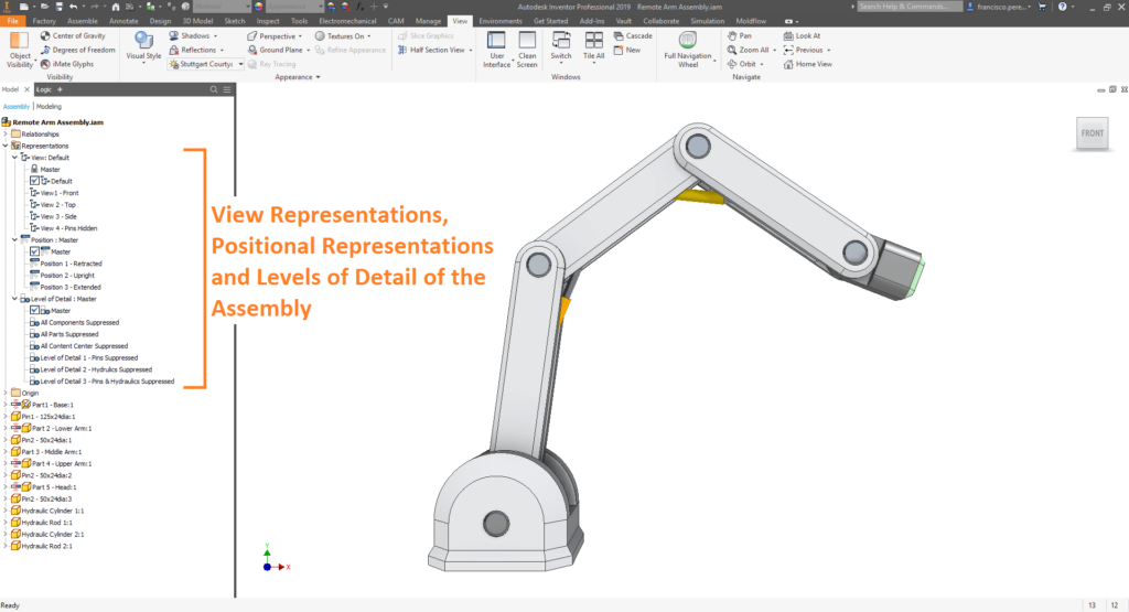
When working with assemblies in Autodesk Inventor, it is sometimes useful to have different representations of the assembly. These are separated into different types: ‘View Representations’, ‘Positional Representations’ and ‘Levels of Detail’. They can each be found under the ‘Representations’ tab of the Assembly Tree, and will be explored in the blog below.

View Representation
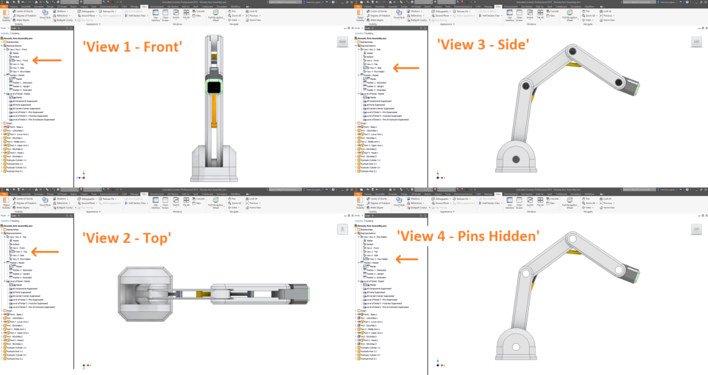
In a nutshell, View Representations preserve an assembly’s display configuration to be recalled later. This is most often used to hide peripheral components so that you can show only components of interest in an uncluttered view.
View Representations can capture the following display characteristics:
- Component visibility,
- Sketch feature visibility, (unless the sketch is turned on or off in the browser).
- Work feature visibility (work planes, work axes and work points),
- Component selection status (‘enabled’ or ‘not enabled’),
- Appearance and style characteristics applied in the assembly,
- Zoom magnification,
- Viewing angle,
- Part view representations.
These can later be recalled within the assembly, or within the assembly’s drawing.

Positional Representation
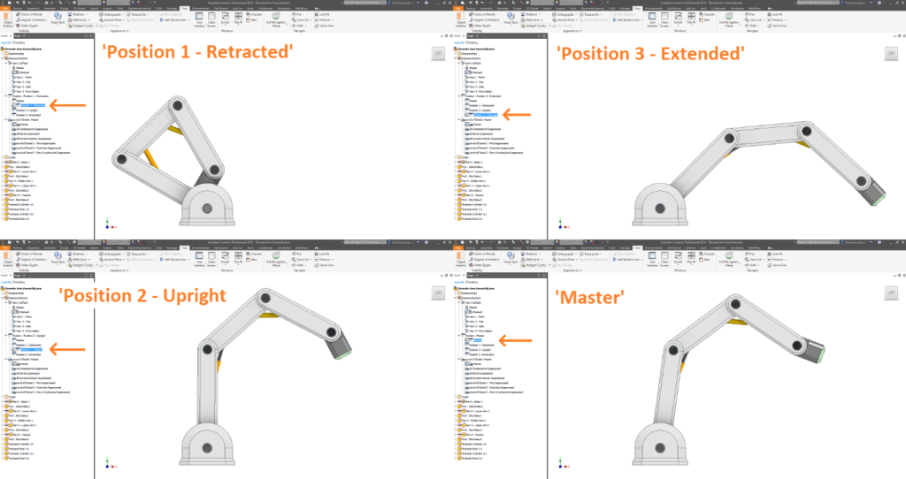
Position Representations serve to capture the position of components in the assembly, including the state of flexible subassemblies. They are extraordinarily useful for later evaluating the assembly in different positions, performing motion studies and producing drawings.
While it is possible to create as many positional representations as you wish, there is a default ‘Master’ positional representation, which serves as the default state of the assembly.
While a positional representation is active, the following may be performed:
- Move a component,
- Change component placement by adjusting a constraint or joint,
- Modify parameters,
- Change flexibility status of subassemblies,
- Turn visibility on and off.
Conversely, with a positional representation active, the following may not be performed:
- Add, delete, or reorder components,
- Restructure the assembly,
- Change the count of a pattern,
- Create or delete work features (work planes, work axes, work points),
- Create, modify, or delete assembly features or iMates,
- Make components adaptive.

Level of Detail (“LOD”)
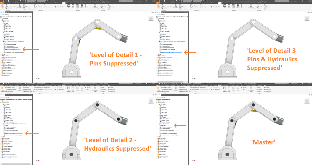
Levels of Detail serve to supress unneeded components, or replace many components with a single part. While their main function is to improve performance by reducing the memory required to work with an assembly, they can be used in conjunction with Positional Representations (discussed above) to customise the visibility and positional state of the assembly’s components. As with View and Positional Representations, Levels of Detail can be recalled later in the assembly or its drawings.

Conclusion
Mastering the use of these representation types can not only improve your efficiency when working with large assemblies, but also enable you to produce higher quality drawings. If you wish to learn Inventor in greater depth, please don’t hesitate to contact Man and Machine, and sign up to one of our master classes.
For more information on this blog post, or if you have any other questions/requirements, please complete the below form:
Related Links
Autodesk Inventor – Man and Machine
Autodesk Inventor Training – Man and Machine
Autodesk Inventor CAM Training – Man and Machine
Autodesk Product Design and Manufacturing Collection – Man and Machine
Inventor Training – Solid Modelling Introduction – Man and Machine
Autodesk Inventor – Autodesk Platinum Partner – Man and Machine


