
In the ever-evolving design industry, manufacturers working in Autodesk Inventor and engineers working in Autodesk Revit, are being required to coordinate their models according to defined BIM processes. Whether you’re designing complex mechanical equipment or planning architectural layouts, the ability to bridge the gap between Inventor and Revit, creates a dynamic and cohesive environment that fosters collaboration and elevates the quality of your outputs. This blog looks at the process of exporting models from Inventor, to be used in a Revit model using the BIM Content Tool.
The BIM Content option is for exporting individual parts or assemblies from Inventor to us within a wider Revit project model. With this option, you also have the flexibility to add MEP Connectors before exporting, which can be used once the model has been converted for use within Revit as a Revit Family file (RFA), for use with open-source applications using IFC format, or as an Autodesk Exchange File (ADSK) – a building component file for transferring manufacturing data between Autodesk programs.
Where can I find the BIM Content Tool?
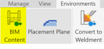
In Inventor, open the Environments tab and select BIM Content from the Begin panel:
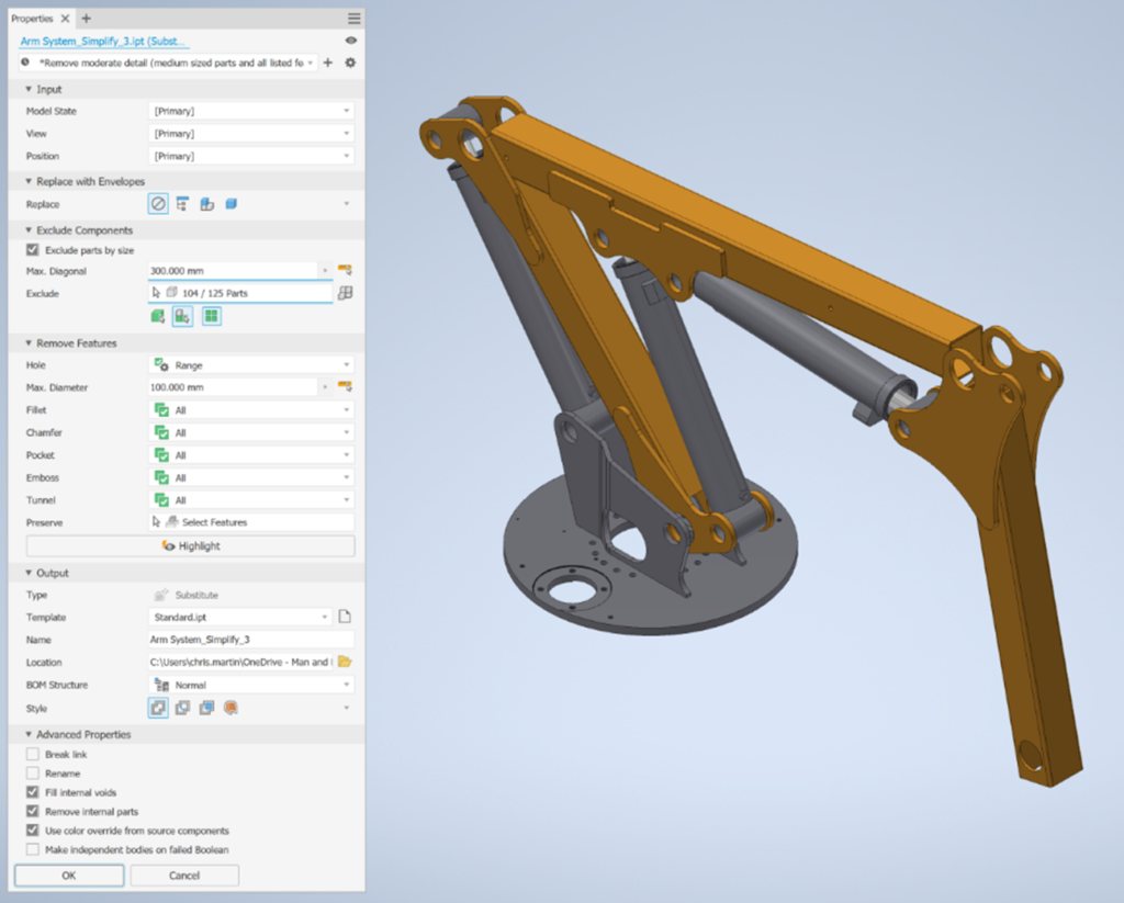
Step 1 – Simplify Your Part or Assembly
Simplify (previously called Shrinkwrap for assemblies) allows you to remove components and features from complex assemblies (and complex parts), in order to make collaboration with Revit easier. Define the settings in the dialogue box as to what is replaced, excluded/removed and how the file will be output to use with other applications.
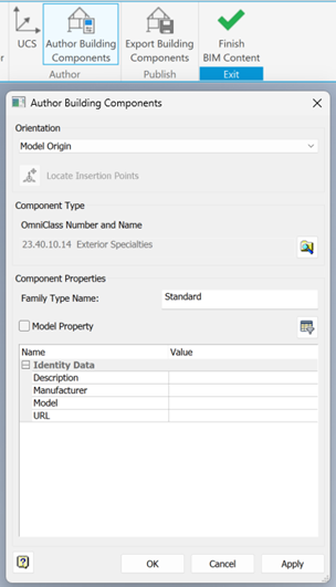
Step 2 – Author Building Components
Orientation
Use Author Building Components and select ViewCube (recommended) or Model Origin from the Orientation dropdown.
If you have created a UCS point, you can also use this in the export process – select the appropriate UCS from the Orientation dropdown.
UCS
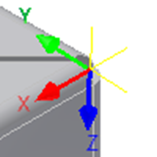
The UCS (user coordinate system) is a collection of work features (three workplanes, three axes, and a centre point).
They are different from the origin in that you can have multiple UCS in one model that can be placed differently, to represent different “model base points”.
The limitation of a UCS is that you can only snap to Work Points and vertices in a part to place a UCS, not an assembly.
If you know the distances between the centre point of the model and where you want your “project base point”/UCS to be placed, then you could set this up, but the best and easiest method would be to use Model Origin or ViewCube as the Orientation when exporting.
Component Type
To define the Component Type, select the magnifying glass-folder icon. The component type is defined by the Omniclass system. In the UK, we use the Uniclass system, so in this case the Product Number and Type is not particularly useful when it comes to exporting, but depending on which you select, you will be given different Component Properties that can be populated with metadata, as well as any custom iProperties that you have created.
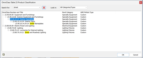
It is also worth defining the Component Type as in the Revit Category column this will push the relevant category through to Revit as a Model Category (e.g. Specialty Equipment, Lighting Fixtures), otherwise the exported RFA will just be defined under the Generic Models category. For this reason alone, we would absolutely recommend classifying your components as necessary to align to the correct Revit Category.
**Note: If you are working with both Inventor and Revit, the category of the exported Family can still be changed by editing the Family once placed in Revit and selecting Family Types.
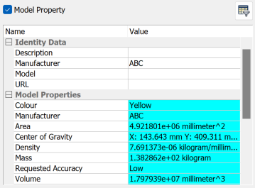
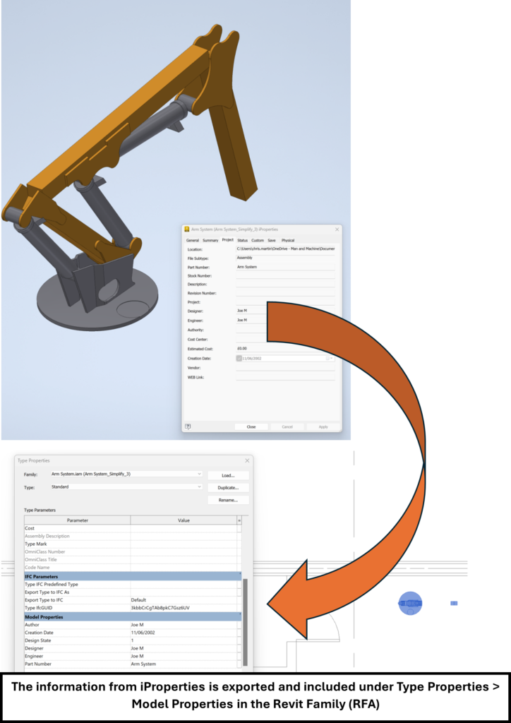
When you check the Model Property checkbox, properties which are mapped from iProperties are shown in blue.
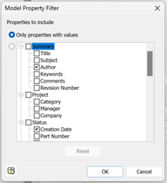
Model Properties to be included in the authoring process can be defined by clicking on the Filter icon. Select Only properties with values, or choose from the list of available Properties. Custom iProperties (including those that have been added to the model with iLogic) will be shown under the Custom list.
Attribute/Metadata Assignment
Attributes can be assigned in iProperties in Inventor and will be transferred with the model when exported out using the BIM Content tool.
Attributes that are exported out by default (with location under iProperties in Inventor) are:
Use the Author Building Components option to include Custom iProperties for CoBie data.
Using iLogic
The iLogic functionality within Inventor is a way of creating a series of rules that run to automate, simplify and speed up processes when working with a model.
- You could develop a series of iLogic rules to do things like updating iProperties, based upon different model criteria, or Replacing Components in an assembly based upon selections made in an iLogic Form, or even updating text blocks within an associated drawing.
- You could also create a script to populate the model’s custom iProperties with fields for COBie data, which can be added in Inventor prior to exporting using BIM content.
- What is COBie? COBie (Construction Operations Building Information Exchange) is a specification used to manage maintainable asset information in a building information model (BIM) workflow. Revit has an Extension as part of the Autodesk Interoperability Tools to be able to export compliant data. In recent times, due to Product Design and Manufacturing businesses often having to be involved in the complete BIM process, fabrication models are becoming more commonly required to conform to COBie standards. Interested in learning all about COBie? The COBie Fundamentals Certification course information is available at the following link: COBie Fundamentals Certification | Man and Machine
- Additional metadata can be added to the part/assembly once in Revit, if required, such as Comments of Mark (Instance parameters) and Type Mark (Type Parameters) – these are default parameters within Revit.
- If you want to add additional new parameters, Edit the Family and add new Family Parameters.
Step 3 – Export Building Components
Export the file as an RFA/IFC/ADSK format. Use the .ADSK format if you have problems with exporting to .RFA. This is more likely to occur if you have a model which contains a high level of detail and/or curvature. If you are just providing outputs to an architect, BIM Coordinator etc, working in Revit, then you are done!
Step 4 – Load the RFA into your Revit Project File (RVT)
If you are also working in the Revit model, exported RFAs from Inventor can be loaded into a Revit project in the same way as a native Revit file. Use either the Component button > Load Family, or Insert tab > Load Family.
As noted previously, when you author with the Orientation as UCS, the placement point of the cursor will be where the UCS is positioned. Otherwise, the model will import with the origin in a central position.
If you cannot see the full extent of the Family in Revit, check the View Range in Properties, Visibility/Graphics in the View tab, and other view-specific settings such as Crop Range.
Conclusion
The advancements in interoperability between Autodesk Inventor and Revit, now offers unparalleled opportunities for collaboration and efficiency in design and engineering workflows, largely untapped even to this day. By combining the strengths of these two platforms, professional can bridge the gap between PDM and AEC design disciplines, ensuring seamless data exchange and better project outcomes.
For more information on this blog post, or if you have any other questions/requirements, please complete the below form:
Related Links
Autodesk Revit – Man and Machine
Autodesk AEC Collection – Man and Machine
Autodesk Revit Training – Man and Machine
Autodesk Revit Demonstrations – Man and Machine
Autodesk Revit – Autodesk Platinum Partner – Man and Machine
Autodesk Revit LT – Autodesk Platinum Partner – Man and Machine
Autodesk Revit LT Suite – AutoCAD & Revit LT – Man and Machine
Revit Architecture Training – Platinum Partner – Man and Machine
Autodesk AEC Collection – Platinum Partners – Man and Machine
Autodesk Inventor – Man and Machine
Autodesk Inventor Training – Man and Machine
Autodesk Inventor CAM Training – Man and Machine
Autodesk Product Design and Manufacturing Collection – Man and Machine
Inventor Training – Solid Modelling Introduction – Man and Machine
Autodesk Inventor – Autodesk Platinum Partner – Man and Machine
Autodesk Product Design & Manufacturing – Man and Machine